www.wimb.net - Electronic Projects
Infra Red
Remote
Control
IR Remote Control
This page describes an Electronic Project that I made in 1983. Therefore some of the components may look a bit outdated. The intention was to make an example application for a small single board computer, in this case with an MK14.
A "real" home computer is a computer where the I/O is connected to the home. For example: lamps, power outlets, windows, doors, curtains etc.
The goal of such a home computer is with the use of the present state of the art technical possibilities to get a life as lazy as possible.
.
Pulses
This system is limited to the transmission of eight pulses on an infrared signal. These pulses are transmitted in serial. The on/off state of a pulse is set with a small switch. These eight switches are divided in two groups: four for an address and the other four for the data. The first group can be used for the "unit" selection and the second group for the actual data.
Since this is not determined in the remote control it self, but by the receiving computer, it can be easily changed to anything else. However, keep it simple, otherwise you'll need another computer to remember the codes.
More pulses
In a future version of the transmitter, it could send a few more pulses, not to control more units, but to send also the ID (identification) number from the sender. With this ID the controlling computer knows from which transmitter the signal comes and it can limit and/or log the control actions from that specific transmitter.

Block Diagram
- Infrared transmitter
- Infrared receiver
- Computer
- Interface
- Real world

IR transmitter
It is built in a plastic box from 112x62x32mm. The eight slide switches are divided in the two groups for address and data. The pushbutton is to send the pulses. Three IR LED's are glued in the short side of the box. The electronic components are placed on a small circuit board of 25 by 55 mm.

The gate U1A and U1B of the 4001 makes an oscillator. This oscillator sets the transmission speed of the pulses (Baudrate). In this case it is about 110 Bd. The second oscillator is made with the gates U1D and U1C. This oscillator makes the high frequency of the Infrared signal.
Relaxation Oscillator

The relaxation oscillator is made from a resistor, a capacitor and an Schmitt inverter. The formulas below can be used to calculate the time and the frequency.

Both oscillators are stopped with a logical high signal on one of the inputs. For U1A this is pin 1 and for U1D pin 13. The IC U2 is a decimal counter-decoder, with ten active high outputs.
In standby pin 11 of U2, the 4017 ten counter/decoder, is high. This is the "9" output of the decoder. This signal is direct connected with U1A pin 1 and it goes via diode D9 to U1D pin 13. Both oscillators are stopped.
When now the start button is pressed then on the reset input of U2 comes a pulse made by the RCR filter between the pushbutton and the reset input of U2. The counter inside U2 goes to zero, pin 11 becomes low and pin 3, the decoded zero output becomes high.
Both oscillators start to operate. The HF oscillator, made by the U1D and U1C, starts to run during the time that the "0" output of U2 is high. It runs at about 40 KHz and drives T1, a TIP122. This gives the HF pulses through the IR led's, which can be seen as the startbit for the receiver. The time that the "0" output of U2 is high is the startbit.
The Baudrate oscillator will only stop when U2, pin 11 goes high. The HF oscillator stops when a switch (SW1 to SW8) is closed. Each closed switch sends via a diode a "1" to the HF oscillator to stop it. Therefore is SW1 for the first data bit, while SW8 is for bit number 8.
In the standby mode the current consumption is almost zero. The biggest current user is the 68k resistor, which is connected to the "stop" output of U2. Also the supply current of the two CMOS IC's is almost zero. Therefore there is no on/off switch for the power supply.
Due to the pulse on the reset input of U2, the start bit is slightly smaller then the databits. This startbit is 6.5 msec, while the databits are 9.2 msec. When the receiver input is a software controlled input on a parallel port then it is not a problem, it means only that the program has to be made for this timing
When a standard serial input is used, then the timing is more critical. It must be set to a standard Baudrate.
A smaller capacitor in the RCR circuit will improve the startbit. Also it may be necessary to do some fine-tuning on the Baudrate oscillator to get a standard output frequency.
The form on the right uses JavaScript to calculate the frequency for a given R and C combination. Be sure to use the correct values.
Construction
The eight switches are glued in the box. The electronic components are placed on a small piece of Vero board. It is very small, so don't make any errors, they are very difficult to correct. Click on the image to have a look inside.

IR Receiver
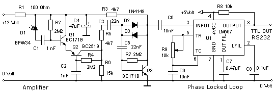
The receiver has two sections, the amplifier at the left side and the Phase Locked Loop detector at the right side of the diagram. Both circuits are more or less standard. The only special is the supply voltage; the amplifier has a 12 V supply and the LM567 is powered by 5 Volt. With the 12 Volt it is easier to get a good amplification and a low noise level. The 5 volt supply to the LM567 makes is possible to connect is direct to an input of a small computer.


The schematic diagram of the amplifier was once copied from a magazine and the diagram for the LM567 comes straight out of the application note, used as frequency detector. The potentiometer R9 must be tuned for the same frequency as send by the transmitter.
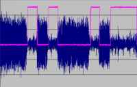
The image at the right shows the modulated HF signal at C6 and the decoded output at pin 8 of the LM567.

Since this receiver is a bit outdated, I recommend to use a newer design.
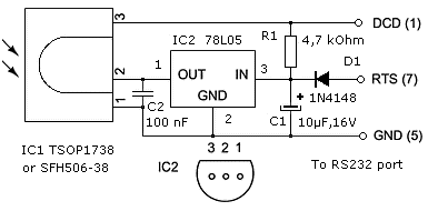
Take for example the circuit on the right. It can be connected direct to the serial port of a PC and there are only a very few parts.
The only problem can be that now the fixed receiving frequency. For the TSOP1738 is it 38 kHz. Now the transmitter has to be set to make this 38 kHz. This can be done by replacing R2 with a variable resistor of about (try) 470 kOhm.

The "Real" Home Computer
The MK14 was a complete microcomputer with a keyboard, a display, 8 x 512 byte pre-programmed PROMs, and a 256-byte RAM programmable through the keyboard. The C.P.U. was a National Semiconductor SC/MP microprocessor.
Interface
Real world
Data Sheets
- MC14001 (PDF 328 Kb)
- MC14017 (PDF 259 Kb)
- LM567 (PDF 297 Kb)
- BPW34 (PDF 93 Kb)
- TSOP1738 (PDF 187 Kb)
Do it yourself
Just buy all the parts, put them together and it works...
No, normally not. Even the smallest project can be a lot of work and frustrations.
A simple way to make something is to buy a kit at electronickits.com. Please note that all links open in same window.
Updated 2007 Oct. 09


