www.wimb.net - Slo-Syn Drives - Indexers
Slo-Syn
Museum

Old Slo-Syn Drives
1960..1975
Translators
STM250
STM1800V
ST1800B
ST1800BV
STM1800CV
HTR103RTX
HTR105RTX
BTR25
BTR50
BTR50L
STM1800D
STM1800DV
Indexers
SP1800BX-4
2SP1800X-4
SA1800
HPI153RX
HPI155R
Old Slo-Syn Drives - Indexers
This page gives an overview of the oldest Slo-Syn stepper motor Indexer drives. It starts with the SP1800BX-4, from around 1966 and the end is around 1975.

Single Axis Preset Indexer SP1800BX-4
SLO-SYN Preset Indexers are used for controlling indexing operations in applications utilizing bifilar SLO-SYN motors for positioning. They automatically provide the correct switching sequence needed to drive the SLO-SYN motors the required number of steps and have provisions for actuating any external equipment needed to perform related operations. Index, jog and free run functions can be initiated manually from the control panel or from an external switch. With proper external switching, a SLO-SYN Preset Indexer can be made to cycle automaticaIIy. Single- and two-axis models are avaiable with counting ranges to 99,999 steps. Two-axis models provide independent control of two SLO-SYN motors.

Principles of Operation
The block diagram in Figure 1 shows the basic elements which comprise tbe SLO-SYN Preset Indexer circuit. These include an adjustable frequency oscillator, control gates, decade counters, and a pulse-to-step translator logic circuit. Depending on the angular movement desired, the correct count is preset on the deci'de counter controls.
A command signal in the form of a switch closure causes the gate circuits to pass pulses from the oscillator to the decade counters and the translator logic circuit. The translator logic circuit converts tbe pulses into the switcbing sequence needed to advance the motor shaft in steps.
When the count is completed, the control gate turns off the pulse gate and actuates a relay which controls any external apparatus being operated in conjunction with the Preset Indexer. The oscillator frequency can be adjusted to vary the stepping speed from four steps per second up to the maximum permissible with the motor used.

The image on the right shows one of the three or four counter boards from the SP1800. It has four Flip-Flops, each made with two transistors. These Flip-Flops can be preset via the four diodes at the bottom of the card. One side of these diodes goes straight to the edge connector, where is goes further to the BCD switches. The whole board is in fact a "Presettable Divide by Ten Counter".
Ten years later it became only one IC, like the SN74190 a "Presettable BCD-Decade Up/Down Counter", now (2004) it is an invisible small part of a chip. If you are wondering what the dark area in the middle is, please have a look to the
other side.

Two-axis Axis Preset Indexer 2SP1800X-4
This is a Two-axis model and is has two separate indexing circuits, each operating independent of the other.
Backlash Take-up Circuit
A backlash take-up circuit that assures accurate positioning with standard lead screws can be added to any preset indexer model. Printed circuit board MLM144060-G1 is ordered and is then plugged into the chassis in place of another board. The indexer is already wired for this board and has a switch on the rear of the unit for turning the take-up circuit on or off.
The backlash take-up circuit compensates for play in a lead screw by always making the final approach to a position from the same direction. When travel is in the plus direction the indexer will drive the motor only the required number of steps. In the minus direction, the motor will take 20 additional steps and then take 20 steps in the plus direction.

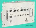
High Speed Indexer HPI153RX/155RX
The 3K and 5K SLO-SYN Preset Indexers drive SLO-SYN Precision Stepping Motors in indexing and other positioning applications. The units will drive the motors at rates up to 3000 or 5000 steps per second, depending on model.
Decade counter controls on the front panel allow the operator to select the desired positioning movement. When the index command is given, the unit will accelerate the motor and drive it at the desired rate until a specific number of steps remains of the preselected count. At this point the unit decelerates the motor, stopping it exactly at the selected point.
The unit then actuates a relay to control any external equipment needed for related operations.

Absolute Preset Indexers SA1800 Series
Absolute Preset Indexers of the SA1800 Series are used to control the stepping motors in indexing and positioning operations. The operator selects the desired positioning increment by setting counter controls on the front panel and presses the INDEX button to start the motion.
The indexer will automatically actuate a relay to energize any external equipment needed to perform related operations. Jog and free run modes of operation are included to cut setup time by allowing movement without the need for setting the counter controls.
ABSOLUTE POSITIONING
When absolute positioning is used, the position or number set on the counter controls is relative to the starting or "zero" point. For example, a setting of 250 would cause the indexer to position the motor 250 steps from the zero point. No further movements could be made until the controls were set to a new count. A new setting of less than 250 would cause the unit to drive the motor in the reverse direction until it was the proper number of steps from the zero point. A higher count would cause the motor to be driven further from the zero point.
INCREMENTAL POSITIONING
In the incremental positioning mode, the indexer will drive the motor the number of steps set on the counter controls each time it is actuated. Movement can be in either the plus or the minus direction.
Updated 2007 Oct. 09


