www.wimb.net - 2010 Shortwave Receiver
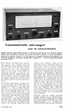
Communication Receiver
 This was a design of Philips made in about 1962. It was a receiver for the Radio Amateur Shortwave bands, the 80, 40, 20, 15 1nd 10 meter bands. The size of the front is 465 mm wide and 200 mm high.
No kit
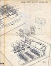
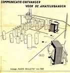 It was not a kit, only the schematic diagram and the construction drawings were supplied. All components had to be bought one by one in a shop. At the right a part of the drawing. It shows the power supply and the IF and LF amplifiers. In the 2010 on the photo's the choke in the power supply was replaced by some resistors. This works fine for low current.
Also the chassis is home made from 4 mm aliminium. All holes are hand drilled and hand cutted.
2-Meter Converter
 Since there was some space left in the unit, it was possible to place a 2-meter converter. This small Printed Circuit Board converts the 2-meter band: 144-146 Mhz to the 10-meter band: 28-30 Mhz.
At that time the most popular modulation on 2-meter was FM modulation and the 2010 had no FM demodulator. However, the narrowband FM was very good detectable on the edge of the signal, with the so called "edge detection".
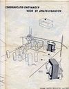
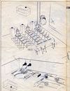
Construction Drawings
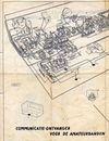
Below all four drawings that I found back after a very long time. Click on a thumbnail to view a larger size.
With javaScript it opens in a popup, without, in the same browser window.
Photo's
Below some of the photo's that were taken about 40 years after its construction. Click on a thumbnail to view a larger size.
With javaScript it opens in a popup, without, in the same browser window.


Construction Drawings
At the right you can see the first page of the Radio Bulletin article from Nov. 1962. Click on it to download the PDF file (600k). Plaese note that it is in the Dutch language. But note that schematic diagrams are international,
Updated 2007 Oct. 09
